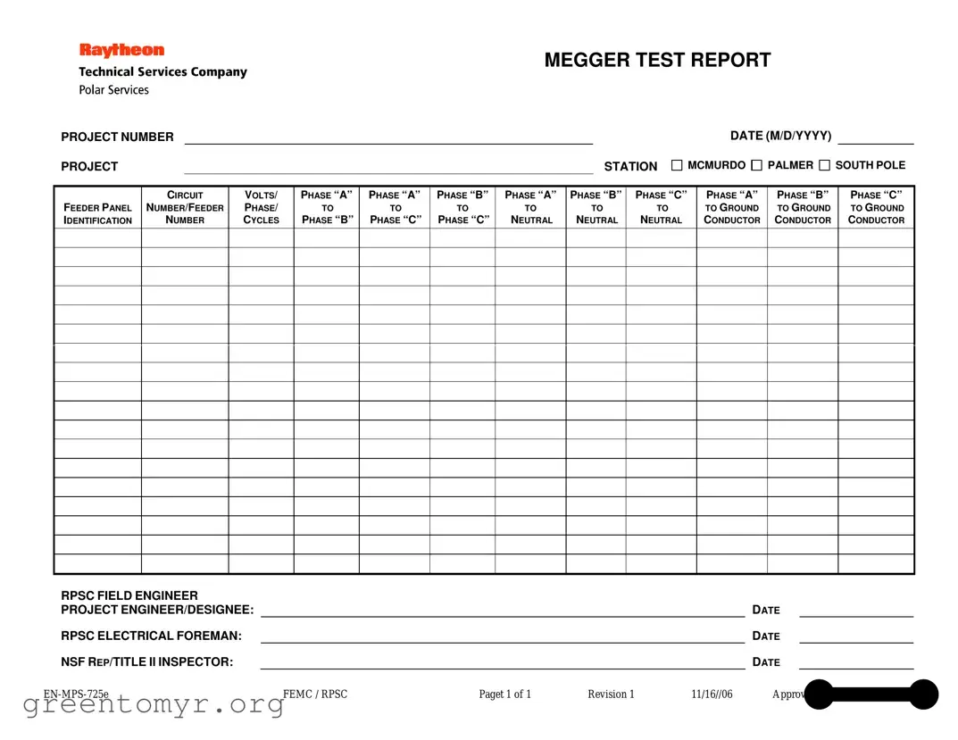
The Megger Test form is an essential tool for assessing the insulation integrity of electrical systems, particularly in challenging environments like those found at research stations in Antarctica. This form captures crucial data, including the project number and specific station details, such as McMurdo, Palmer, and South Pole. It meticulously records various measurements across different phases, including voltage readings between phase pairs and to neutral, as well as ground connections. Each entry is critical for evaluating the performance of electrical circuits, ensuring safety, and maintaining compliance with industry standards. The form also includes spaces for signatures from key personnel, such as the RPSC field engineer and the project engineer or designee, underscoring the collaborative nature of these assessments. By documenting the test results and relevant identifiers, this form serves not only as a record of compliance but also as a reference for future maintenance and troubleshooting efforts.
MEGGER TEST REPORT
PROJECT NUMBER
PROJECT |
|
STATION |
DATE (M/D/YYYY)
MCMURDO PALMER SOUTH POLE
FEEDER PANEL IDENTIFICATION
CIRCUIT
NUMBER/FEEDER
NUMBER
VOLTS/
PHASE/
CYCLES
PHASE “A”
TO
PHASE “B”
PHASE “A”
TO
PHASE “C”
PHASE “B”
TO
PHASE “C”
PHASE “A”
TO
NEUTRAL
PHASE “B”
TO
NEUTRAL
PHASE “C”
TO
NEUTRAL
PHASE “A”
TO GROUND CONDUCTOR
PHASE “B”
TO GROUND CONDUCTOR
PHASE “C”
TO GROUND CONDUCTOR
RPSC FIELD ENGINEER |
|
|
|
|
|
|
PROJECT ENGINEER/DESIGNEE: |
|
|
|
|
DATE |
|
RPSC ELECTRICAL FOREMAN: |
|
|
|
|
DATE |
|
NSF REP/TITLE II INSPECTOR: |
|
|
|
|
DATE |
|
FEMC / RPSC |
Paget 1 of 1 |
Revision 1 |
11/16//06 |
Approved by Wayne L. Cornell |
||
| Fact Name | Details |
|---|---|
| Project Number | This unique identifier helps track the specific project associated with the Megger test. |
| Project Station | The form indicates the location where the Megger test is conducted, such as McMurdo, Palmer, or South Pole. |
| Date | The date of the test is recorded in the format M/D/YYYY, ensuring clarity and consistency. |
| Feeder Panel Identification | This section identifies the specific feeder panel being tested, crucial for maintenance records. |
| Circuit Number/Feeder Number | Identification of the circuit number or feeder number allows for precise tracking of electrical systems. |
| Voltage and Phase Information | Details about voltage, phase, and cycles are essential for evaluating the electrical system's performance. |
| Ground Conductor Testing | Tests between phases and ground conductors assess the safety and integrity of the electrical system. |
| Field Engineer and Project Engineer | Signatures from the RPSC field engineer and project engineer/designee ensure accountability and oversight. |
| Approval and Revision Information | The form includes revision details and approval by Wayne L. Cornell, indicating its validity and authority. |
Filling out the Megger Test form is essential for documenting electrical tests conducted on various circuits. Completing this form accurately ensures that all relevant data is captured for future reference and compliance. Follow these steps to fill out the form correctly.
A Megger Test is an electrical test used to measure insulation resistance in electrical systems. It helps identify potential issues such as insulation breakdown, which can lead to equipment failure or safety hazards. This test is crucial for ensuring the reliability and safety of electrical installations.
The Megger Test form includes various essential details such as:
The results on the Megger Test form are presented as resistance values measured in ohms. Each measurement indicates the insulation resistance between different phases and between phases and ground. Higher resistance values typically indicate better insulation quality, while lower values may suggest potential issues that need to be addressed.
The Megger Test should be conducted by a qualified electrical technician or engineer. This individual must have the necessary training and experience to ensure accurate results and safe testing practices. The form must then be signed by the field engineer and the project engineer/designee to validate the test results.
The frequency of Megger Tests depends on several factors, including the type of equipment, environmental conditions, and regulatory requirements. Generally, it is recommended to conduct these tests during initial installation, after any major repairs, and at regular intervals based on the manufacturer's guidelines or industry best practices.
If the Megger Test results indicate low insulation resistance, immediate action should be taken. This may involve:
Consulting with a qualified electrical professional is advisable to determine the best course of action.
Filling out the Megger Test form accurately is crucial for ensuring the integrity of electrical systems. One common mistake occurs when individuals fail to include the project number. This number is essential for tracking and referencing the test report in future communications. Without it, the report may not be linked to the specific project, leading to confusion.
Another frequent error is neglecting to specify the feeder panel identification. This identification is vital for understanding which panel the test results pertain to. Omitting this information can result in miscommunication among team members and stakeholders, potentially compromising safety and efficiency.
People often overlook the date section of the form. Providing an accurate date is necessary for record-keeping and project timelines. If the date is missing or incorrect, it can create challenges in verifying when tests were conducted and may affect compliance with regulations.
Inaccurate voltage and phase information is another mistake that can occur. The form requires specific details about volts, phase, and cycles. Incorrect entries in these fields can lead to improper assessments of electrical systems, which may pose safety risks. It is essential to double-check this data before submission.
Additionally, individuals sometimes forget to fill in all the phase-to-phase and phase-to-neutral measurements. Each measurement is critical for a complete understanding of the electrical system's performance. Missing any of these can lead to incomplete evaluations and potential oversights in system maintenance.
Another common error is not having the field engineer and other responsible parties sign off on the form. Signatures confirm that the information provided has been reviewed and validated. Without these signatures, the report may lack credibility and could be questioned later.
People also frequently misinterpret the section for ground conductor measurements. Accurate readings are essential for ensuring that the grounding system is functioning properly. Errors in this section can lead to significant safety hazards, making it imperative to pay close attention when recording these values.
Finally, individuals may neglect to keep a copy of the completed Megger Test form for their records. Retaining a copy is crucial for future reference and can be invaluable in the event of audits or inspections. Proper documentation practices help maintain accountability and transparency throughout the project lifecycle.
When conducting electrical testing, several documents complement the Megger Test form. Each of these documents serves a specific purpose, ensuring that testing is thorough and meets safety standards. Below is a list of commonly used forms along with brief descriptions.
These documents work together to ensure a thorough and safe testing process. Maintaining accurate records is crucial for compliance and future reference.
The Megger Test form is an important document used in electrical testing, but it shares similarities with several other forms. Each of these documents serves a specific purpose while capturing essential information related to electrical systems. Here are four documents that are similar to the Megger Test form:
Understanding these similarities can help ensure that electrical testing and maintenance are conducted effectively, leading to safer and more reliable systems.
When filling out the Megger Test form, it’s important to ensure accuracy and completeness. Here are four essential do's and don'ts to keep in mind:
By following these guidelines, you can help ensure that the Megger Test report is clear and useful for all parties involved.
Misconceptions about the Megger Test can lead to confusion and improper use of this important electrical testing method. Here are ten common misconceptions:
When filling out and using the Megger Test form, there are several important points to keep in mind. These guidelines will help ensure accuracy and compliance with testing standards.
By following these key takeaways, you can ensure that the Megger Test form is filled out correctly and used effectively, contributing to the overall safety and reliability of the electrical systems being tested.